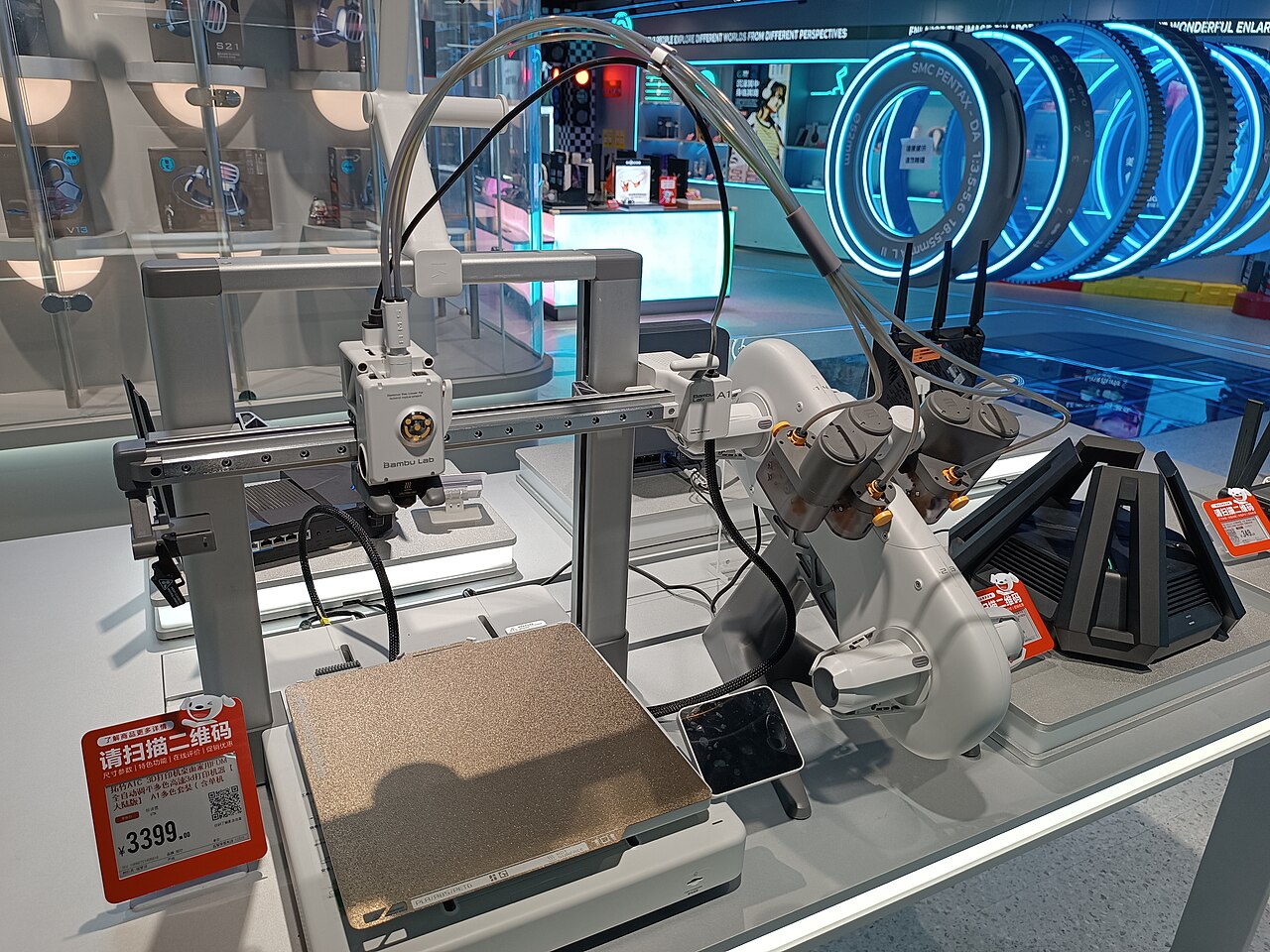
The Bambu A1’s 410 mm body depth is only the starting point for planning its workspace. In an official A1 quick-start guide, Bambu illustrates 198 mm of clearance behind the printer and 90 mm in front. Adding those reservations to the listed body depth gives a preliminary front-to-back reference of 698 mm, or about 27.5 inches.
That figure describes a clear operating-space calculation for the cited arrangement. It is not a certified minimum tabletop depth or a complete A1 Combo station size. You still need a stable support surface, room for the feeder and spools, and access to the printer. Use the guide supplied for your own printer and feeder arrangement before settling its position.
Start with three different measurements
It helps to separate the printer’s body, its clear operating space and the whole station. They answer different questions.
| Measurement | What it tells you | What it leaves out |
|---|---|---|
| A1 chassis: 465 × 410 × 430 mm | The manufacturer’s listed body dimensions | Moving-bed clearance, feeder placement and handling access |
| Referenced depth calculation: 698 mm | Body depth plus the cited front and rear reservations | Complete station width, service access and another arrangement’s requirements |
| Your complete station | The printer, chosen feeder, spools, cables and access in their actual positions | Nothing should be assumed from the chassis figure alone |
The chassis dimensions come from Bambu’s current A1 product information. They are not the shipping-box dimensions, and the 256 mm print volume is a different measurement again. A printer that makes a 256 mm part does not occupy a 256 mm square of desk.
For the clearance reference, this guide uses the official Dutch A1/AMS lite quick-start PDF, identified as PF002-A/SA005, footer 01. Its printed pages 20–21 show the feeder arrangement and front/rear reservations. Other layouts or revisions need their own check.
Check the clear space in front of and behind the printer
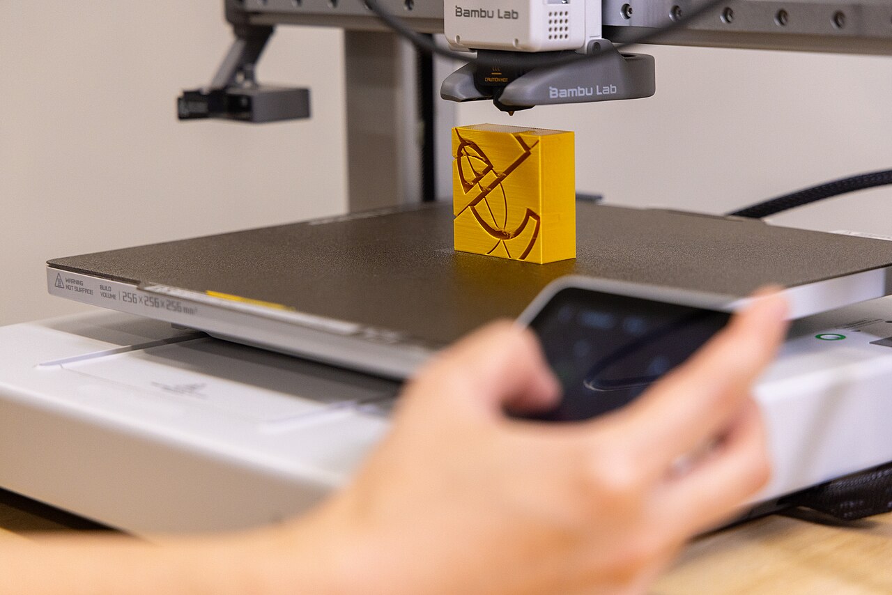
Measure the space that will remain unobstructed, rather than entering the desk’s advertised depth automatically. A wall, shelf support, monitor stand or item left behind the printer may reduce that clear space.
The reference arithmetic is:
410 mm body depth + 198 mm behind + 90 mm in front = 698 mm.
The tool below compares your available front-to-back clear space with that reference. It checks this one dimension; it does not approve the support surface, a different layout or the whole installation.
Reference depth check
Check your clear operating depth
Compare available front-to-back clear space with the guide’s provisional 698 mm illustrated reservation. This checks clear operating depth only, with tabletop support checked separately.
Reference: 410 mm body depth + 198 mm rear + 90 mm front = 698 mm. This reservation belongs to the illustrated PF002-A/SA005 reference used in the guide. It does not establish a 698 mm minimum tabletop depth or authorize overhang. Verify your actual manual, stable base support, width, feeder, cables and service access.
For a hypothetical 650 mm clear-space allowance, the reference is 48 mm longer. A hypothetical 762 mm allowance, equivalent to 30 inches, leaves 64 mm beyond the reference. The second result means the depth calculation is met; it does not establish room for the feeder or give the installation an overall pass.
Measure the stable surface supporting the printer separately. Neither the calculation nor a positive tool result authorizes an unsupported base or a particular overhang arrangement. Check the actual setup instructions and the support surface as well as the surrounding clear volume.
Give AMS lite its own place in the plan
The ordinary A1 Combo includes AMS lite as a separate feeder. In the cited guide’s illustrated side arrangement, Bambu recommends a 50 mm gap between the A1 and AMS lite. The drawing also shows the routing of the filament tubes and data cable.
That gap is a spacing instruction for the pictured arrangement, not the station’s total width. Drawing two rectangles with a 50 mm gap is a useful sketch, but it cannot account for mounted spools, their orientation, cable paths and the room you need to change them.
Before deciding where AMS lite belongs, identify:
- The exact feeder and arrangement shown in your current instructions.
- The space occupied with the spools actually installed.
- The route of the tubes and cable, including their connection points.
- The access needed to load, unload or replace a spool.
Bambu’s AMS lite product information supplies its own dimensions, but adding that chassis width to the A1’s width is not a universal complete-station measurement. The orientation of the feeder and the fitted spools matter.
Keep a changed feeder or mount out of this calculation
A top-mounted feeder is a different arrangement. The A1’s listed 430 mm chassis height does not describe the height of that complete station. Use the mounting instructions, supported hardware and actual access needs for the chosen arrangement; the side-layout drawing cannot settle them.
Likewise, AMS lite and AMS 2 Pro are different devices. The current A1 information describes using larger AMS generations through a separate A1-series hub. That does not make the AMS lite layout’s spacing a placement rule for the larger feeder.
If you are considering AMS 2 Pro because of its drying function, read our guide to drying power and printer-dependent modes. Feeder compatibility, drying power and physical placement need separate answers.
Do not apply these A1 numbers to an A1 mini, A2L or a different printer. A similar appearance is not evidence of identical movement or clearance.
Make a station sketch before moving everything
A useful sketch records more than a single desk dimension. Start with your actual printer and current instructions, then mark these areas:
| Area to mark | Question to answer |
|---|---|
| Stable support | Is the printer’s base supported by a suitable, stable surface? |
| Rear and front clear space | Which instructions apply, and what could obstruct the stated reservations? |
| Feeder and fitted spools | Where will they sit, and can you reach the spools and connections? |
| Cable and tube routes | Can the documented routing be followed without an obstruction? |
| Handling access | Can you remove the build plate, reach controls and perform the required maintenance? |
Treat this as a list of requirements to check, not a new set of manufacturer-approved clearances. The source diagrams provide particular dimensions; the sketch makes sure the rest of your own arrangement has not been forgotten.
Avoid choosing a cabinet simply because the printer’s body fits inside it. Bambu’s A1 FAQ discourages enclosing the A1. The body dimensions alone cannot establish an enclosure or a room’s suitability.
The measurement to take away
Use 698 mm as the preliminary clear-depth reference derived from the cited A1/AMS lite arrangement. Then check the current instructions, stable support, feeder and spool layout, and handling access separately.
If one of those checks fails, revise the arrangement before treating the desk as ready. If the depth reference is met, the next useful measurement is the space needed by your actual feeder and fitted spools—not another look at the printer’s box size.

.jpg)
_Step_1.jpg)